Announcement

Collapse
No announcement yet.

Control 24vac hvac dampers with this?

Collapse
X
 
  • Filter
  • Time
  • Show
Clear All
new posts

    #16
    Thanks so much for the hand holding! It makes some sense now. I assume I'd be smart to get something like this http://www.makershed.com/products/ma...e-jumper-wires and this http://www.makershed.com/products/de...d-jumper-wires to make the connections?

    also, I have plenty of 5v wall warts, what amperage would you recommend for powering each of the relay boards? and just to be clear - that's to power the board, right? the HVAC dampers I have are all powered by a 7.5 amp 24Vac supply...I'll wire that in with the relay channels.

    Thanks,

    Ian
    Plugins:
    BLLogMonitor, BLGarbage, BLBackup, BLOutGoingCalls, BLUps, BLRfid, JvEss, DooMotion, Applied Digital Ocelot, AC RF Processor, UltraMon, PJC AVR 430, UPB, Rain8net, DSC Panel, JRiver Media center, Windows Media Player, SageMediaCenter, SnevlCID, MCSTemperature.

    Comment


      #17
      Originally posted by completelyhis View Post
      Thanks so much for the hand holding! It makes some sense now. I assume I'd be smart to get something like this http://www.makershed.com/products/ma...e-jumper-wires and this http://www.makershed.com/products/de...d-jumper-wires to make the connections?

      also, I have plenty of 5v wall warts, what amperage would you recommend for powering each of the relay boards? and just to be clear - that's to power the board, right? the HVAC dampers I have are all powered by a 7.5 amp 24Vac supply...I'll wire that in with the relay channels.

      Thanks,

      Ian
      Yes, the male to female jumpers will work fine for connections between the Arduino and relay board. You could also splice a mail and female end on the connections from your wall wart. Put a female on the "+" and a male on the "-". Connect the "+" to the relay board VCC and the "-" to the Arduino GND. Then connect a male to female jumper between the GND on the Arduino and the relay board. After you have it all working, use some hot melt glue or RTV to bind the connections to the boards so they don't come loose. Those jumpers don't have a lot of mechanical grip.

      Any 5V wall wart will do. Just remember to connect the "-" to both the relay board and the Arduino, because the GND is common for the logic as well as the relay coil return. Each coil on the relay is probably 5-10ma so all 8 on at once would be less than 1/10a. The wall wart only supplies power for the relay coils. Your dampers would be connected through the Common and N.O. connections on the relay contacts. On my hydronic system, each valve is operated by a little 24V synchronous motor, so I supply one side of the 24V to each motor, the other side of the 24V to all the relay common terminals. Then one N.O. contact goes to each of the motors second connection.
      Last edited by randy; November 30, 2014, 12:08 PM.
      HS4 Pro, 4.2.19.16 Windows 10 pro, Supermicro LP Xeon

      Comment


        #18
        Man I'm such a noob! I connected my Arduno, and I read the help file for the plugin, but I just don't get it. Here are some questions:
        1. I am using USB, what do I do with the comport setting, leave it blank?
        2. I have 2 relay board connected (each with 8 relays), do I configure that in the plugin setup, telling it that each (22-whatever) is a "whatever" - input, output, servo" - if so, which whatever would a relay be?

        I did install the arduno software, as well as the plugin. I guess, in short, I just don't get how it works. "It" being the board, the USB, and the plugin, and the relationship between them all. I've got the plugin installed, and the hardware connected, but it wasn't magically all ready :-)
        Plugins:
        BLLogMonitor, BLGarbage, BLBackup, BLOutGoingCalls, BLUps, BLRfid, JvEss, DooMotion, Applied Digital Ocelot, AC RF Processor, UltraMon, PJC AVR 430, UPB, Rain8net, DSC Panel, JRiver Media center, Windows Media Player, SageMediaCenter, SnevlCID, MCSTemperature.

        Comment


          #19
          Originally posted by completelyhis View Post
          Man I'm such a noob! I connected my Arduno, and I read the help file for the plugin, but I just don't get it. Here are some questions:
          1. I am using USB, what do I do with the comport setting, leave it blank?
          2. I have 2 relay board connected (each with 8 relays), do I configure that in the plugin setup, telling it that each (22-whatever) is a "whatever" - input, output, servo" - if so, which whatever would a relay be?

          I did install the arduno software, as well as the plugin. I guess, in short, I just don't get how it works. "It" being the board, the USB, and the plugin, and the relationship between them all. I've got the plugin installed, and the hardware connected, but it wasn't magically all ready :-)
          This will be a very long answer - I will try to walk you through it tomorrow. You're almost there.
          HS4 Pro, 4.2.19.16 Windows 10 pro, Supermicro LP Xeon

          Comment


            #20
            Originally posted by completelyhis View Post
            Man I'm such a noob! I connected my Arduno, and I read the help file for the plugin, but I just don't get it. Here are some questions:
            1. I am using USB, what do I do with the comport setting, leave it blank?
            2. I have 2 relay board connected (each with 8 relays), do I configure that in the plugin setup, telling it that each (22-whatever) is a "whatever" - input, output, servo" - if so, which whatever would a relay be?

            I did install the arduno software, as well as the plugin. I guess, in short, I just don't get how it works. "It" being the board, the USB, and the plugin, and the relationship between them all. I've got the plugin installed, and the hardware connected, but it wasn't magically all ready :-)
            I'll try to do this step by step. I may end up editing this post if I realize any errors after the fact. Some of this you already may have done.

            First some definitions:
            • Output: sends a high (5V) or low (0V) signal to some other device
            • Input: receives a high (5V) or low (0V) digital input from some other device. These inputs are pulled high by an internal resistor so a switch wired between the input pin and GND would read high with the switch off and low with it on.
            • Analog In: this is an input to read a varying level input and convert it to a value. This input can vary between 0V and 5V and must not exceed 5V.
            • PWM: a Pulse Width Modulated output generally used to control the brightness of an LED. The output is a square wave with the on time varied between 100% and 0%, but always 5V during the time it is on and 0V during the time it is off.
              [*}RGB a device that combines 3 PWM channels into a single RGB control specifically for control of LED devices with RGB outputs.
            • Servo: this is an output designed to drive a servo device


            All of the above is in the Arduino plug-in help file accessible fron the upper left corner of the plug-in configuration page.

            You are going to use "output" to drive your relays.

            Hopefully you have installed the Arduino software on the same machine you are running HomeSeer on. After you install the Arduino software you MUST copy the additional and modified Libraries to the Arduino software installation location usually c:\Program Files (x86)\Arduino\Libraries if it is a 32 bit version of Windows the (x86) will not be there.

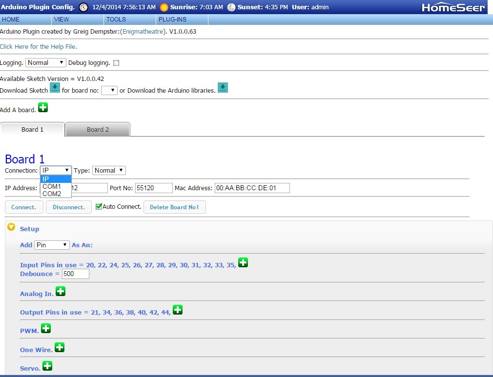
            Your Arduio board will be assigned a COM port when it is connected to the computer. In most cases the computer will have COM1 and COM2 assigned and when you plug in the Arduino it will be assigned COM3 or some other COM above 2. There are a number of ways to determine what is assigned, the easiest for you might be to go to the plug-in configuration page, with the Arduino unplugged. Click the Connection drop down and note the COM ports offered. Then plug in the Arduino, reload the configuration page, click the Connection drop down and note the COM port that is added - that will be your new Arduino board. Below is a screenshot of mine with no Arduino USB connections made. The version number in the screenshot below is a beta release and should not be used in production. Your version should be the current production release of V1.0.0.36.


            Set the Connection to the new COM port, then download the sketch for the board. There will be a "Download Sketch" (or Firmware depending on plug-in version) button "for board no:" select board 1 and click the arrow to download the properly configured sketch. The sketch will be located in your Homeseer Config directory, usually c:\Program Files (x86)\HomeSeer HS3\Config\Arduino Config\HomeseerBoard1.ino.

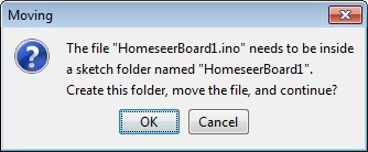
            This is the sketch you will upload to the board using the Arduino software. If you click on the HomeSeerBard1.ino sketch, it will automatically launch the Arduino software and load the sketch. You will see a warning:


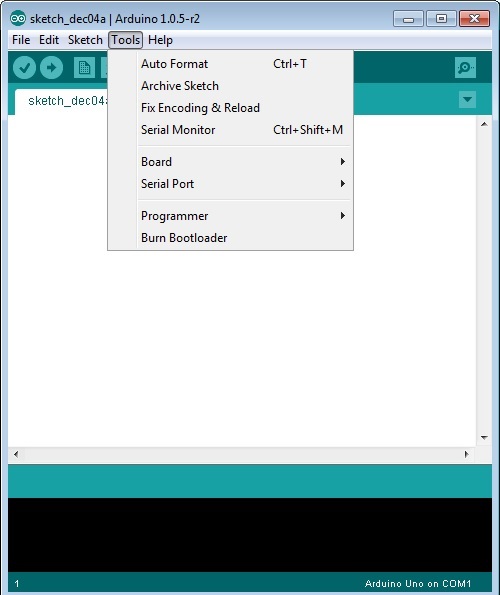
            Click "OK". Then you will need to configure the board type (Mega, Uno, etc.) and the Serial Port from the "Tools" drop down.


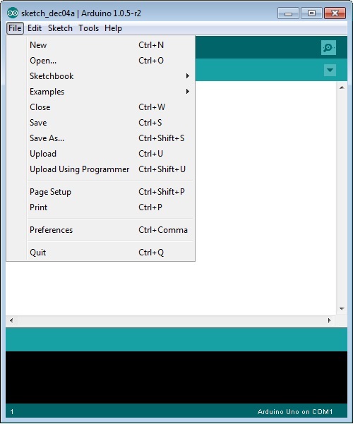
            Then select "Upload" from the "File" drop down.


            Once the sketch is uploaded (the software will say "Done Uploading" at the bottom), close the Arduino software and reset the board by pressing the reset button. You should now be able to connect it to HomeSeer. Click the Connect button and select the Auto Connect check box.

            You can now add pins 22, 24, 26, 28, 30, 32, 34 and 36 as Outputs. There will be eight devices created in the HomeSeer Device Manager with On and Off controls which can be manually controlled or controlled by events like any other binary device. As i said in an earlier post if your On and Off controls are reversed at the relay, your relay board has the incorrect configuration but there is a workaround.

            The plug-in help file has all the information you need, I have just provided more detail.

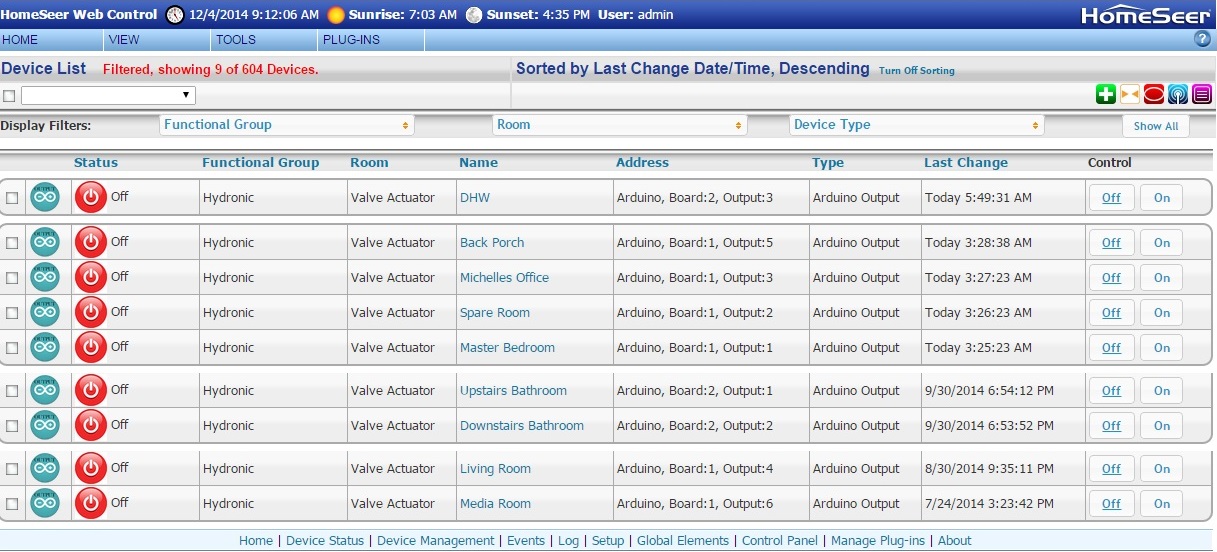
            Below is a screenshot of the 9 outputs I created for valve actuators in my heating system. I changed the status graphics to more correctly show the status than the default light bulbs.

            Last edited by randy; December 4, 2014, 10:50 AM.
            HS4 Pro, 4.2.19.16 Windows 10 pro, Supermicro LP Xeon

            Comment


              #21
              I got an error message, "Could not create the sketch folder", likely because of permissions and such, so I did it in the "documents" folder. when I clicked "upload" I got the error shown in the screen shot.

              let me know if I should start a new thread for this! and thanks so much for all the help!
              Attached Files
              Plugins:
              BLLogMonitor, BLGarbage, BLBackup, BLOutGoingCalls, BLUps, BLRfid, JvEss, DooMotion, Applied Digital Ocelot, AC RF Processor, UltraMon, PJC AVR 430, UPB, Rain8net, DSC Panel, JRiver Media center, Windows Media Player, SageMediaCenter, SnevlCID, MCSTemperature.

              Comment


                #22
                What is the error, the screenshot is not readable. It looks like a screenshot of the sketch within the Arduino software.
                HS4 Pro, 4.2.19.16 Windows 10 pro, Supermicro LP Xeon

                Comment


                  #23
                  sorry about that. try this:

                  HomeseerBoard1:188: error: 'OneWire' does not name a type
                  HomeseerBoard1:189: error: 'DallasTemperature' does not name a type
                  HomeseerBoard1:190: error: 'DeviceAddress' does not name a type
                  HomeseerBoard1.ino: In function 'void OneWireCheck()':
                  HomeseerBoard1:198: error: 'sensors' was not declared in this scope
                  HomeseerBoard1:201: error: 'tempDeviceAddress' was not declared in this scope
                  HomeseerBoard1.ino: In function 'void DataEvent()':
                  HomeseerBoard1:447: error: 'sensors' was not declared in this scope
                  HomeseerBoard1:450: error: 'tempDeviceAddress' was not declared in this scope
                  Plugins:
                  BLLogMonitor, BLGarbage, BLBackup, BLOutGoingCalls, BLUps, BLRfid, JvEss, DooMotion, Applied Digital Ocelot, AC RF Processor, UltraMon, PJC AVR 430, UPB, Rain8net, DSC Panel, JRiver Media center, Windows Media Player, SageMediaCenter, SnevlCID, MCSTemperature.

                  Comment


                    #24
                    Originally posted by completelyhis View Post
                    sorry about that. try this:

                    HomeseerBoard1:188: error: 'OneWire' does not name a type
                    HomeseerBoard1:189: error: 'DallasTemperature' does not name a type
                    HomeseerBoard1:190: error: 'DeviceAddress' does not name a type
                    HomeseerBoard1.ino: In function 'void OneWireCheck()':
                    HomeseerBoard1:198: error: 'sensors' was not declared in this scope
                    HomeseerBoard1:201: error: 'tempDeviceAddress' was not declared in this scope
                    HomeseerBoard1.ino: In function 'void DataEvent()':
                    HomeseerBoard1:447: error: 'sensors' was not declared in this scope
                    HomeseerBoard1:450: error: 'tempDeviceAddress' was not declared in this scope
                    It looks like you never installed the additional libraries, or installed them in the incorrect path as required by the sketch. You need to download the libraries and install them in the Arduino software program folder on the host computer. It is outlined in the documentation.
                    HS4 Pro, 4.2.19.16 Windows 10 pro, Supermicro LP Xeon

                    Comment


                      #25
                      ahh, maybe i need to move them to the same folder i moved the sketch file to (when win8 wouldn't let it create the folder). Thanks, i'll give it a go!

                      btw, your screenshots and explanations are stellar!
                      Plugins:
                      BLLogMonitor, BLGarbage, BLBackup, BLOutGoingCalls, BLUps, BLRfid, JvEss, DooMotion, Applied Digital Ocelot, AC RF Processor, UltraMon, PJC AVR 430, UPB, Rain8net, DSC Panel, JRiver Media center, Windows Media Player, SageMediaCenter, SnevlCID, MCSTemperature.

                      Comment


                        #26
                        Originally posted by completelyhis View Post
                        ahh, maybe i need to move them to the same folder i moved the sketch file to (when win8 wouldn't let it create the folder). Thanks, i'll give it a go!

                        btw, your screenshots and explanations are stellar!
                        No!

                        The libraries go in the program files folder on your computer.

                        If you are running 64-bit Windows it is:
                        C:\Program Fies (x86)\Arduino\Libraries


                        If you are running 32-bit Windows it is:
                        C:\Program Fies\Arduino\Libraries

                        When you download the Libraries from the Arduino plug-in, the individual folders in the folder above. It will overwrite some.
                        HS4 Pro, 4.2.19.16 Windows 10 pro, Supermicro LP Xeon

                        Comment


                          #27
                          Any 5V wall wart will do. Just remember to connect the "-" to both the relay board and the Arduino, because the GND is common for the logic as well as the relay coil return. Each coil on the relay is probably 5-10ma so all 8 on at once would be less than 1/10a. The wall wart only supplies power for the relay coils. Your dampers would be connected through the Common and N.O. connections on the relay contacts. On my hydronic system, each valve is operated by a little 24V synchronous motor, so I supply one side of the 24V to each motor, the other side of the 24V to all the relay common terminals. Then one N.O. contact goes to each of the motors second connection.
                          Rprade,

                          SUCCESS! Thanks so much! so before I wire my dampers into the relays, I just need to make sure I understand how. I've included a diagram of how it is now w/Rain8net, and my confusion. basically, the rain8 has one common port for all 8 zones, so i ran it via a bus. it also has a pos/neg for the power that goes to the dampers.

                          the diagram is a bit confusing. the "com" is "common" coming from the bus. the +/- coming from the 7.5 amp transformer go into the +/- on the rain8.

                          the Arduino relays seem to be different. I'm thinking this will be my last obstacle, then i'm home free! Thanks again for all the help. I'd buy you a coffee/brewskie if i knew your paypal! :-)
                          Attached Files
                          Last edited by completelyhis; December 23, 2014, 11:10 PM. Reason: clarification
                          Plugins:
                          BLLogMonitor, BLGarbage, BLBackup, BLOutGoingCalls, BLUps, BLRfid, JvEss, DooMotion, Applied Digital Ocelot, AC RF Processor, UltraMon, PJC AVR 430, UPB, Rain8net, DSC Panel, JRiver Media center, Windows Media Player, SageMediaCenter, SnevlCID, MCSTemperature.

                          Comment


                            #28
                            Originally posted by completelyhis View Post
                            Rprade,

                            SUCCESS! Thanks so much! so before I wire my dampers into the relays, I just need to make sure I understand how. I've included a diagram of how it is now w/Rain8net, and my confusion. basically, the rain8 has one common port for all 8 zones, so i ran it via a bus. it also has a pos/neg for the power that goes to the dampers.

                            the diagram is a bit confusing. the "com" is "common" coming from the bus. the +/- coming from the 7.5 amp transformer go into the +/- on the rain8.

                            the Arduino relays seem to be different. I'm thinking this will be my last obstacle, then i'm home free! Thanks again for all the help. I'd buy you a coffee/brewskie if i knew your paypal! :-)
                            It would wire similarly to your Rain8Net. Since the transformer is 24VAC there is no polarity and both wires are likely the same color. Using your drawing lets call the black wire out of your 24V transformer "common" - it would connect to the common of both your dampers just like before. Lets call the red wire "hot" - it would go to the common terminal of both (or all) relays. The common terminal is usually the center one of each relay and should be labeled "C" on the PC board. Then a wire would go from the terminal labeled "N.O." on each relay to the corresponding damper's wire which was going to the Rain8net.
                            HS4 Pro, 4.2.19.16 Windows 10 pro, Supermicro LP Xeon

                            Comment


                              #29
                              like this?

                              Is the attached drawing accurate?
                              Attached Files
                              Plugins:
                              BLLogMonitor, BLGarbage, BLBackup, BLOutGoingCalls, BLUps, BLRfid, JvEss, DooMotion, Applied Digital Ocelot, AC RF Processor, UltraMon, PJC AVR 430, UPB, Rain8net, DSC Panel, JRiver Media center, Windows Media Player, SageMediaCenter, SnevlCID, MCSTemperature.

                              Comment


                                #30
                                Originally posted by completelyhis View Post
                                Is the attached drawing accurate?
                                Like this if you want one relay to control each damper.
                                Attached Files
                                Last edited by randy; December 24, 2014, 03:52 PM.
                                HS4 Pro, 4.2.19.16 Windows 10 pro, Supermicro LP Xeon

                                Comment

                                Working...
                                X